Working with markers in a Well View
While you can visualize marker data using the Well View, you can also use the floating palette () in the Well View to pick new markers for an existing marker set. When picking new markers in this manner you select a destination marker set, name, and specify the type of marker being picked. After this information has been specified you can then perform the picking process. Surface data, any surface in your solution or from interpretations and other models (e.g. fault model, structural model), can be added to the view to aid in the QC process of your picked markers.
-
Use the JewelExplorer to display all of the wells and other well data that you wish to use during the picking process in the Well View.
- Open the floating palette (Tools > Editing Tools) and click the Create Marker icon
 ; a number of options related to marker picking will appear in the floating palette.
 -
Select the Marker Set from the drop-down list to which you want to add a marker.
-
Give the new marker a name.
-
Select what kind of surface the new marker represents. If you select Fluid Contact as the type you can specify the fluid above and below the contact.
- Choose one of the wells in the Well View and click at the point of interest to add the marker. This will turn on the picking mode and add the marker to the well. The marker will now also be available in the JewelExplorer under the Marker Set you picked in the previous steps.
- Press Ctrl to add a second marker of the same name to the same wellbore.
- Press Shift to add a Constraint marker.
- Press Shift + Ctrl to add a second Constraint marker to the same wellbore.
-
Continue until you have finished picking the markers. Click the Pick and Move Marker icon
 again or press Escape to disable the picking mode.
Though the easiest method of deleting a marker is to right-click the marker in the JewelExplorer and select Delete from the context menu, this results in the deletion of the marker from all wells. If you wish to delete markers one at a time, or from a specific well, you can do so in the Well View:
- In the Well View display the wells and markers that you wish to delete.
- In the track for the well that you wish to delete the marker from, right-click the marker and click Delete from the context menu. This will remove the marker from the Well View, you can also confirm in the 3D view that the marker has only been removed from the specific well, and not from all wells as it would have been had you deleted it from the JewelExplorer.
- In the Well View, display the wells and the markers that you wish to adjust.
- Open the floating palette (Tools > Editing Tools) and turn on the picking mode by clicking the Pick and Move Marker icon .
- Hover over the marker you want to adjust, the cursor will change to a pair of arrows
 indicating that the marker can be moved.
 - Click the marker and adjust as desired. When finished adjusting markers click the Pick and Move Marker icon again or press Escape to disable picking mode.
Any of the markers can be selected as the primary datum. There are two ways of selecting a primary datum:
- Via the drop-down list in the Well View toolbar.
- By right-clicking the marker of interest in the Well View and selecting Set as Primary Datum. After setting marker as primary datum, the view will refresh based on your selection.
You can bind a horizon well marker and a fault well marker when they coincide in the wellbore. This typically occurs when the wellbore penetrates a fault which truncates a zone. Note that, in order to bind a horizon well marker and a fault well marker, they need to be in the same Marker Set. For more information, see Binding markers.
- In the Well View, display the fault well marker and the horizon well marker that you want to bind.
- Open the floating palette (Tools > Editing Tools) and click the Bind Markers icon
 .
. - Click successively on the fault well marker and the horizon well marker. The horizon marker will move to the position of the fault well marker and a bind symbol
 appears in the left most track in the Well View. In the Marker Table, the Bound To column displays the relevant markers.
To unbind two markers, click the Unbind Markers icon  in the floating palette and then click on the bind symbol in the left most track of the relevant well. Note that after unbinding, the horizon well marker has adopted the depth of the fault well marker.
You can validate markers for stratigraphic consistency. JewelSuite Geomechanics will check whether markers in the Well View are picked conform the stratigraphic order of the Stratigraphic Model; any marker that diverts from that order, will be added to the 'Invalid Markers' table on the form. You can also generate a zone correlation backdrop on the Well View to aid you in marker picking. For more information, see Marker validation in the Well View.
- In the Well View, display the wells for which you want to validate markers, because the 'Invalid Markers' table can only contain invalid markers of displayed wells.
- Open the Marker Validation form by clicking the Validation button
 in the Well View toolbar.
 - Select the relevant Stratigraphic Model and Marker Set from the Model and Marker set drop-down lists respectively: only the events that are present in both data sources are taken into account during the validation.
- Optionally, check the Show backdrop based on stratigraphic level checkbox and select a stratigraphic level from the drop-down list, if you want to generate a backdrop of correlated zones in the Well View. The backdrop automatically updates during marker picking and when changing marker positions. The backdrop takes the colors of the zones in the stratigraphic model.
- Click Apply: all identified 'Invalid markers' are added to the 'Invalid markers' table on the form.
- Optionally, click the second Show Invalid markers button
 to indicate 'invalid' markers with an exclamation mark. Note that, for the exclamation marks to be displayed, the markers need to be visualized in the view.
Any of the surfaces available under the Imports or Data folder in the JewelExplorer, or any of your models (e.g. fault model, structural model, fluid model), surface sets or interpretations, can be visualized in the Well View by checking its box in the JewelExplorer.
- In the JewelExplorer, locate the surfaces that you want to add to the view.
- Check the box for each of the surfaces you want to add to the view.
In the following QC example, the solid orange line is the marker, while the dashed orange line represents the C60 horizon.
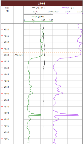
Marker-horizon mismatch example. The solid orange line is the marker, while the dashed orange line represents the C60 horizon. click to enlarge